Resonator method Technical overview
Features and benefits
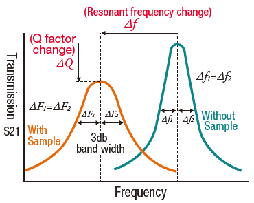
In the resonator permittivity measurement method, the material parameters are obtained from the change in resonance caused by placing the measurement sample in the resonator. The permittivity is obtained from the change in frequency, and the dielectric loss is obtained from the change in Q value. Since even a small change in loss due to the insertion of a low-loss sample can result in a large change in Q-value, low-loss can be measured accurately, which is the major advantage of this method.
The resonator method can be further classified into several techniques depending on the measurement frequency. The following is a description of the key technologies that characterize the various resonators we provide.
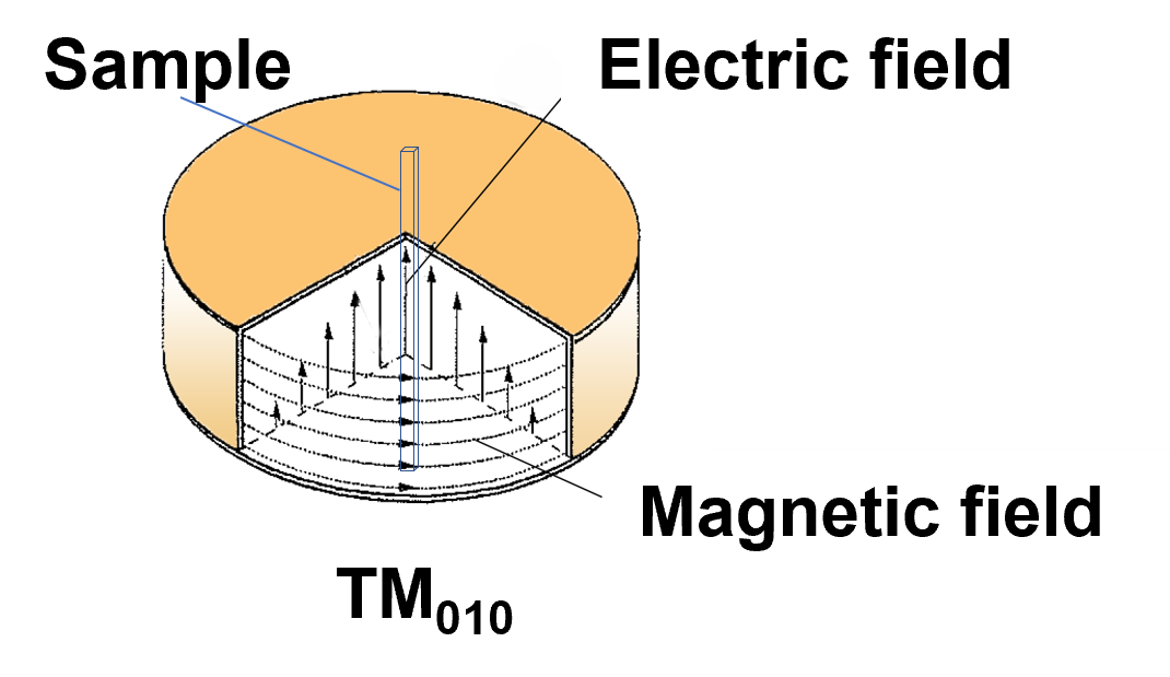
Cavity resonators for 1 GHz measurements
The CP series measures the permittivity from 1 GHz to 10 GHz using the TM010/020 mode resonance that occurs in a cavity resonator. In this resonance, the center of the cylinder is the area where the electric field is greatest, and by inserting a rod-shaped sample into this area, the permittivity is measured using the electric flux along the sample. It is possible to evaluate anisotropy by changing the direction in which the sample is cut out.
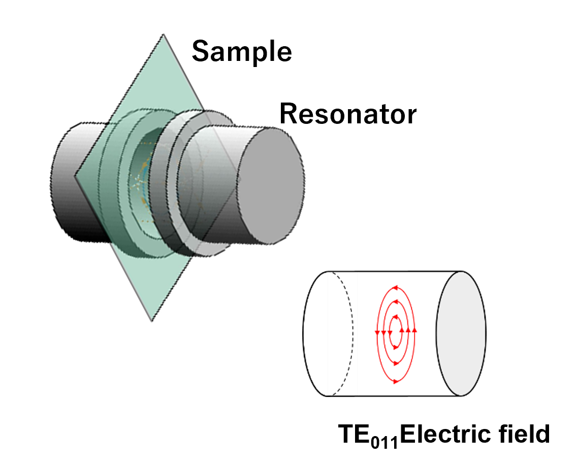
Split cylinder for measurements up to 80 GHz
In the split-cylinder resonator method, the resonator is split in the middle and a plate sample is placed between the two. In the case of the CP series resonators, imperfections at both ends of the flux in the sample can cause measurement errors. This effect is more pronounced at higher frequencies where the sample is shorter. The split cylinder uses the TE011 mode of resonance, where the electric flux circulates in the sample plane, eliminating the negative effects of "ends" and allowing accurate measurements up to high frequencies.
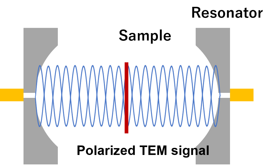
Fabry-Perot resonator for frequency multipoint measurements up to 330 GHz
The FP series uses polarized TEM modes signal generated in an open-type resonator, and its primary advantage is that even high frequencies such as 330 GHz can be realized with a practical-sized test fixture. (To achieve this frequency as an extension of the split cylinder, a resonator with a diameter of less than 1 mm must be made with impractical precision.) Another important feature is that multiple resonances suitable for permittivity measurement can be generated in a wide frequency range. By making good use of this, it is possible to evaluate the frequency characteristics of the permittivity with a single fixture. In addition, since polarized signal is used, anisotropy can be evaluated by rotating the sample.